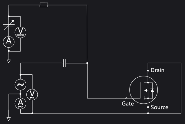
FET: Rg, Cgg-Vg Test
Measures the internal gate resistance, Rg, of the device. The device must have a gate oxide. In IC-CAP and the PEMG software the gate resistance is calculated from the Cox, also known as Cgg or Cg. Cgg = Cgs + Cgd + Cgb. Requires the N1272A Device Capacitance Selector SMU.
Used with:
-
B1506A: FET DUT
- B1505A: FET DUT, CV test type
- If the data sheet lists a maximum test limit for a parameter, use that value.
- If there is no maximum test limit, use a typical value.
See also Setting IV and CV Test Parameters.
Test Schematic
Gate Parameters
Click here for detailed information about each item in the list.
VGSStart (V): The VGS sweep start voltage (V).
VGSStop(V): The VGS sweep stop voltage (V).
Drain Parameters
Click here for detailed information about each item in the list.
SweepOutput: Use the drop-down menu to choose the scale of sweep:
Linear - Linear sampling (see also the LinearNOS setting)
Log10 - 10 points/decade log sampling
Log25 - 25 points/decade log sampling
LOG50 - 50 points/decade log sampling
LinearNOS: The number of steps for LINEAR sweep scale (see the SweepOutput option).
Frequency (Hz): The Measurement signal frequency (in Hz). NOTE: Keysight recommends that you use a 100 kHz measurement frequency when using the B1506A for this test (due to an additional error of its device capacitance switch).
Example
In this example FET device is used as the example test device.
This device has the following basic characteristics.
- VDSS: 40 V
- Rds(on): Typ. 1.35 mΩ @ Vgs=10 V)
- ID max.: 350A @ 100 μs pulse, VD=10V, 1390 A @ Vd=2.5 V
- Coss: 2360 pF typ. @ Vd=25 V
- Rg(int): 6.8 Ω typ.
Setup
- Choose FET as device type.
- Select the checkbox for Rg, Cgg-Vg test.
General settings
- Set 1 MHz as measurement frequency
Gate Voltage Sweep
- Leave as initial settings (-3 V to 3 V, LinearSingle)
Collector / Drain Voltage Bias
- Leave as an initial setting (0 V).
Click the Start button
The Rg is measured immediately at VGS = 0 V is 5.48 Ω.
